Jennings restoration

After doing those "reinforcing plates", I wasn't pleased to find a patch of rot on one of the other outriggers. The one in front of the forward spring hanger with the brace attached. It looked pretty small, but grew a bit when poked! A bit awkward, this one. I unpicked the front end of the brace, then was able to cut off the outrigger. I cut it horizontally to avoid having to weld to my newly painted floor.

2015122202254_2015_0121Commer0007.JPG


This outrigger doesn't have a top closer pate fitted, as it only supports the floor, so it just fills up with cr@p through the gaps between the top and the floor. Yes I did check the other side. Clean as a whistle. Strange.

So now all the welding has been done from the bulkhead rearwards.

Next job was to waxoil inside the chassis and all the underside. Clear waxoil in the chassis, and black over everything visible. I decided against my usual black bitumen paint, giving the black waxoil a try, as it is easier to spray.

2015122203041_2015_0121Commer0008.JPG


Photos didn't come out too well, cos it's black as a coal cellar down there now.

2015122203156_2015_0121Commer0010.JPG


Haven't decided what to do with that bashed rear quarter valance yet. I'll probably just cut it off. The near side has been cut off anyway. It's not doing any good.

That's got to be progress.

Now I have to break off to earn a living for a while.

It will give the paint and waxoil a chance to dry off...........

Commer PB Jennings
 
Very tidy[^]
What is it about the rear panels under a Jennings - what was the original number plate panel on Bonnie looks like it's bee hit with an axe, I think some people must think it's OK to put a jack under them[xx(]

41fa30c8-22ce-43e8-bd12-188475a80292.jpg
 
So...........

Yesterday I reassembled the axle, ready to go back on.

2015128212119_2015_0127Commer0006.JPG


Refitted the springs, and found that a G cramp with a large socket was a good tool to push the shackles through the rubber bushes.

2015128211959_2015_0127Commer0002.JPG


I soon had the axle refitted.

2015128212043_2015_0127Commer0007.JPG


Then I read Iceman's thread about his wheel coming loose, so this morning the axle came back off again to check and improve thelocknut arrangement. I've put some pictures of that over on his thread.

Now the axle is back on for the second time, and I've started on the overdrive.

More of that later.


Commer PB Jennings
 
Splendid[^]
Isn't it amazing how these little tricks develop in isolation - I did exactly the same thing with the shackle bushes:)

41fa30c8-22ce-43e8-bd12-188475a80292.jpg
 
I have osteoarthritis in my hands, so I have to find ways of doing things without much force or grip. Necessity being the mother of invention, as they say. But it all takes longer than it used to.

Commer PB Jennings
 
Cant grip the big hammer as tightly as you used to;)
Arthritis or not you do a cracking job.

41fa30c8-22ce-43e8-bd12-188475a80292.jpg
 
Got the overdrive adaptor back ffrom the engineers, so made a start on buttoning up the gearbox/overdrive.

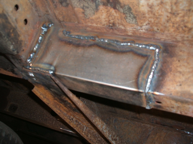
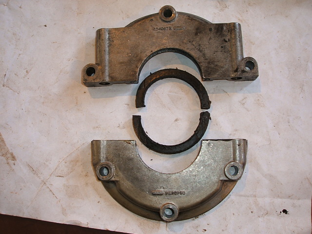
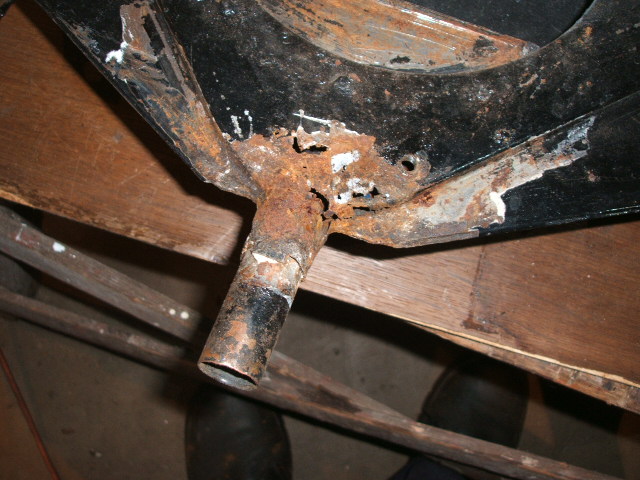
Here's the casting, but without the feet.

201512921014_2015_0127Commer0003.JPG


You can see the welding repair to the craacks, and I don't need the feet anymore, because I've redone the mounting.


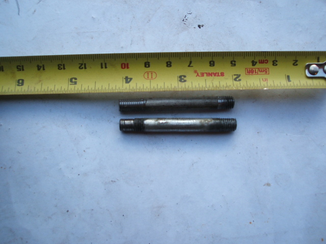
First job was to replace some of the studs which connect the overdrive to the adaptor casing. Previously, these studs had been part of the support for the engine and gearbox. I was surprised to see they were 1/4 UNF at both ends, and some of the ends tapped into the overdrive were only 1/4 inch long. Now that's not a lot of support, so the new ones had better be good. (and not done up too tight!)

201512921543_2015_0128Commer0001.JPG


All the more reason to use a different mounting method.

I had bought a gasket and O ring kit off Sheffield Overdrive repairs.

First the actuator piston O rings were replaced. Easy.

201512921731_2015_0128Commer0002.JPG


Then the solenoid, valve, and pump O rings were all replaced. No photos here, as I can't add anything to this fantastic article at http://www.buckeyetriumphs.org/technical/jod/JOD1/JOD1.htm which I relied on for the job.

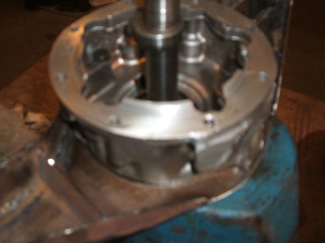
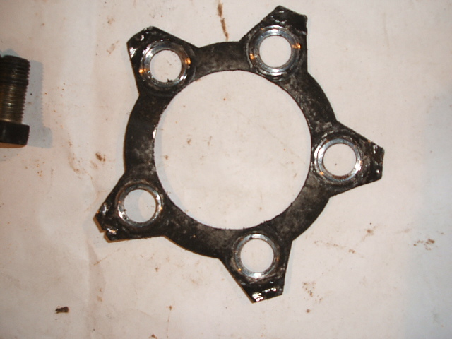
The new mount was sandwiched between the adaptor and gearbox (I had had 2mm machined off the adaptor to make way for the mounting plate).

201512921183_2015_0128Commer0003.JPG


That's a dreadful photo. I think the auto focus on my old camera is getting temperamental!

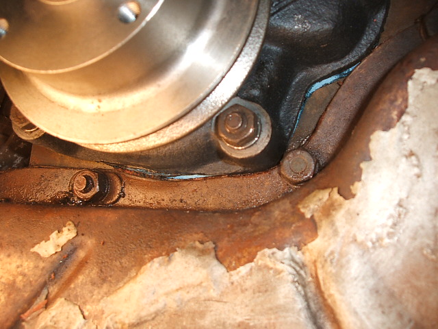
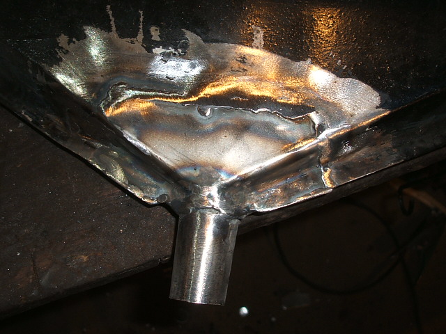
Here's the completed gearbox.

2015129212045_2015_0128Commer0004.JPG


You can see that the weight is now taken without imposing any stress on the overdrive unit itself. It's all taken by the cast iron gearbox.

A few mods to the selector housing on top to improve operation of the overdrive switch, and the whole lot is ready to go back on the engine.

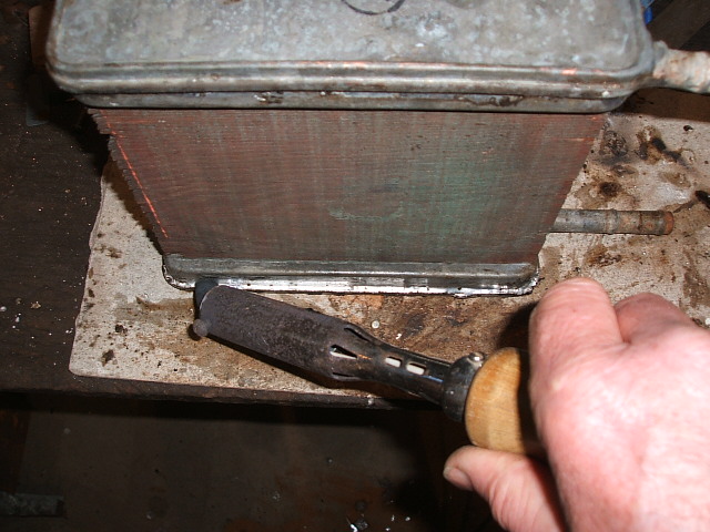
Next job will be to replace the rope type rear crank seal on the engine. This is evidently the Achilles Heel of the Perkins, and I'd be mad not to do it while the gearbox is out.

Commer PB Jennings
 
The Perkins rear crank oil seal is like this.

2015130214857_2015_0129Commer0001.JPG


It consists of ptfe woven rope (original was asbestos!) in two channels which clamp around the crank like this.

2015130215050_2015_0129Commer0003.JPG


Incidentally the bolts that hold the adaptor plate to the back of the engine were only finger tight! The mind boggles.

The flywheel would go on next, but this is the kind of tab washer you can't re-use.

2015130215312_2015_0129Commer0002.JPG


The tabs have already been bent up, then back down, so would have no strength if bent up again. I don't make tab washers like this, but discard them and use heavier grade loctite instead.

Flywheel back on, and a piece of scrap angle to lock against the ring gear teeth while tightening the flywheel and clutch bolts. Oh, and not forgetting to grease the spigot bearing.

2015130215657_2015_0129Commer0004.JPG


I couldn't be arsed to make a dummy input shaft so lined up the clutch plate carefully by eye and hoped for the best!

201513021592_2015_0129Commer0005.JPG


Gearbox went straight on first time. Result!

2015130221735_2015_0129Commer0006.JPG


Now I have to reconnect the linkages.

Does anyone have any advice on adjusting the gearchange linkage please? I understand they can be a bit of a problem.


Commer PB Jennings
 
Try it the way it came off without adjusting anything first, you never know it might be OK. If you do have trouble then it's most likely the bushes on the operating lever, cheap and pretty easy to do. Martin Maltas does them.

41fa30c8-22ce-43e8-bd12-188475a80292.jpg
 
The gear linkage was very stiff when connected up. The problem seemed to be the cross shaft between the chassis bracket and the UJ on top of the gearbox. The bracket was re-aligned, and a sliver welded into the front leg, and Hey Presto, it all worked fine.

Today I took off the leaking water pump, and promptly dropped it against the radiator core!
So the rad had to come off to solder up the little hole I'd just made (good job it's made of copper and brass then). It would have had to come off anyway I suppose, as the next job was to flush out the cooling system. Just who is responsible for designing that throttle bracket bolted to the side of the rad?

The rad was easy to flush out at this point, and the water pump was temporarily replaced to flush the engine. Hose in the thermostat hole, and some old downpipe and guttering to carry the water outside..........


..........until it all ran clean, but I've had problems in the past with the cooling systems of older engines clogging up with sediment behind cylinder 4, leading to local boiling when working hard. I don't want this happening again, so I needed to find a way of making sure it had all been cleaned out. Luckily, there is a drain cock in just the right place, so I hunted through my plumbing junk, made up a hose-pipe-to-1/4NPT adaptor and used it to blast mains pressure straight into the back of the water jacket behind cylinder 4.

20152321355_2015_0202Commer0002.JPG


I'm glad I did, because a huge
amount of muck came out.

When I fitted the new water pump, I had another little disaster. The casting interfered with the timing cover so when I tightened it up it broke the edge off the pump casting.

20152321409_2015_0202Commer0005.JPG


You can see where the pump casting had marked the edge of the timing cover Luckily, there was still plenty of facing to seal against the gasket, so no great harm done, but it left me wondering if the manufacturers had ever fitted one of these. Then I checked the old water pump and found that it had been ground away to clear in the same place.

While I'm in there, I'd better have the alternator out and check it over tomorrow.


Commer PB Jennings
 
While I had the rad and fan belt off, it was a good time to check over the alternator. The original 10AC type (with remote regulator under the dash) had been changed for a 16ACR (integral regulator) at some time, and some of the 5/16UNF bolts had been changed for 8mm, and the wrong way round, so the alternator couldn't be removed without draining the cooling system. Imagine finding that on a dark wet night in a layby! No better time to sort this lot out!

The alternator checked out OK, and the brushes still have plenty of life left.

201525204818_2015_0204Commer0002.JPG


When I tried to fit the fanbelt, it was obvious that the water pump pulley was at least 1/4 inch out of line with the crank pulley. So I had to take the w/p off AGAIN to change the pulley for the old one. With the old pulley pressed on it all lined up perfectly.

There was a starting problem, often with just a click when you turn the key. Here was the problem.

201525205158_2015_0204Commer0003.JPG


I crimped and soldered a new earth lug on the earth strap.

On to the heater, as I knew the matrix had a slight leak.

Behind the dash panel I discovered a right old rat's nest of wiring.

201525205454_2015_0204Commer0004.JPG


The leak from the heater matrix was from the seal around the tanks, which had to be soldered up. My technique here is to warm the whole thing up with a hot air gun, then while hot, use the big soldering iron with plumbers flux and solder to fill up the seams. Time consuming to drive out all the muck which floats out on the new solder, but worth it.

201525205814_2015_0204Commer0005.JPG


No heater repair would be complete without patching up the air box, would it?

20152521228_2015_0204Commer0008.JPG


I guess I'm lucky with this one. Relatively little rot, but still an awkward little welding job.

20152521420_2015_0204Commer0009.JPG


I suppose there must have been some kind of foam sealing strip around the edge of the air flap to seal it against the front bodywork opening. Does anyone know what this was (ie foam or rubber) and how thick it should be? My first thought would be to use ordinary foam draught strip, but should I be using something more specialised?

Commer PB Jennings
 
Started to look into the electrics in more detail. First job was to remove all the modifications, both good and bad to try to get back to the original. Removed the regulator and relay for the original 10AC alternator. Also removed the fuse box because I shall be fitting new ones to fuse all the circuits individually. Whilst working under the dash I found this.
201527171819_2015_0206Commer0002.JPG


Ouch!

That's the main feed from alternator to ignition switch that has burned. Presumably due to a short in the ignition switch (which has been replaced for a petrol one). No wonder the key was the wrong number.

So some deep surgery on the wiring harness will be needed. All the loose wires in the engine bay are brittle, so if I'm taking the harness apart I might as well replace these too, and include the new stuff in the wiring harness.

I'm trying to get a shopping list together of all the electrical wiring products. Can anyone help me with the front sidelight and indicator types. Mine has had some more modern ones fitted and the lenses have been stuck on with silicone, as they tend to fall off really easily. Original type would appear to be Lucas L691 like this for the separate items http://www.autoelectricsupplies.co.uk/product/384/category/72 ,but I'd appreciate some confirmation before I order.

Commer PB Jennings
 
Getting well stuck in:)
The fresh air flap face is normally completely covered with a high density foam, hopefully you can find one that doesn't soak up too much water[xx(]
The lenses are correct, just checked on Harvey:)

41fa30c8-22ce-43e8-bd12-188475a80292.jpg
 
I also keep those lights and separate lenses in stock

www.commervanspares.co.uk
https://www.facebook.com/commervanspares
 
Thank you both for your help.

I've got some old Karrimat foam, right thickness..........but it's bright yellow!
I've also got black, but it's too thick.......might have to try to cut it down a bit.

Commer PB Jennings
 
Looking good Colin, look like you've been busy. The wiring doesn't look to good.

Member of the non-Facebook club.
 
Right.........pulled out the relevant parts of the wiring harness.

2015291962_2015_0207Commer0001.JPG


Peeled off the harness tape to reveal the extent of the damage.

20152919713_2015_0207Commer0002.JPG


The trick here is not to let the harness fall apart, by using zip ties at every branch and at six inch intervals. Then it's just a case of replacing wires on a like for like basis.

20152919825_2015_0209Commer0017.JPG


You can see that although the big brown wire is badly melted, it hasn't really done much damage to the other wires. Just some light local melts which can be easily heatshrink sleeved, then harnessed back up. Now I've been able to order all the electrical stuff to put it all back together.

While doing this I came across some bodgery of the highest order...........

201529191738_2015_0209Commer0018.JPG


I thought you'd like that! I might as well adapt the radio cut-out for a new stereo as it's already there.

While I'm waiting for the electrical stuff to arrive, I welded the fuel tank.

201529192046_2015_0209Commer0020.JPG


Naturally, there was more rust than I originally thought, but still a straightforward weld. No scope for chicken pooh welding here. I was able to use special equipment for fume extraction from the tank, so the only advice I can give is DON'T WELD FUEL TANKS.

Then a quick coat of epoxy resin with glass tissue over the top half of the tank to reinforce the pitted bits. Ready for painting tomorrow.

Commer PB Jennings
 
Back
Top