
You are using an out of date browser. It may not display this or other websites correctly.
You should upgrade or use an alternative browser.
You should upgrade or use an alternative browser.
The New Project
- Thread starter Suinnyboy
- Start date

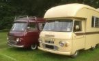

My sparky said that my alternator doesn't need the voltage regulator as it's inbuilt just plugs into the dash light
and there is a connection for the taco, scored.
That column looks the part very modern indeed, one thing he said was the water temp switch on the motor might not sink with the dash gauge
being from different cars either the gauge will start straight to hot then cool or stay at hot, he seemed sure it wouldn't be a
problem for him. Half to a full day and it's all done he recons, but not until next week till i can fire her up, don't weather i can last that long.
The 4 blade thermo fan i had fitted he said won't cut the mustard so he will supply me one that will then i'll remount it before he starts rewiring
Such is Life

and there is a connection for the taco, scored.
That column looks the part very modern indeed, one thing he said was the water temp switch on the motor might not sink with the dash gauge
being from different cars either the gauge will start straight to hot then cool or stay at hot, he seemed sure it wouldn't be a
problem for him. Half to a full day and it's all done he recons, but not until next week till i can fire her up, don't weather i can last that long.
The 4 blade thermo fan i had fitted he said won't cut the mustard so he will supply me one that will then i'll remount it before he starts rewiring
Such is Life

Yes the Smiths Temp gauge may not like the original sender unit, I have ordered my VDO gauges and should have then next week. From previous experience the Nissan temp senders work with VDO's, hope that hasn't changed as I ordered the Temp gauge without a sender, I'll test it prior to installation to be sure.
Yes I have a surround for the Indicator/Wiper stalks Panky.
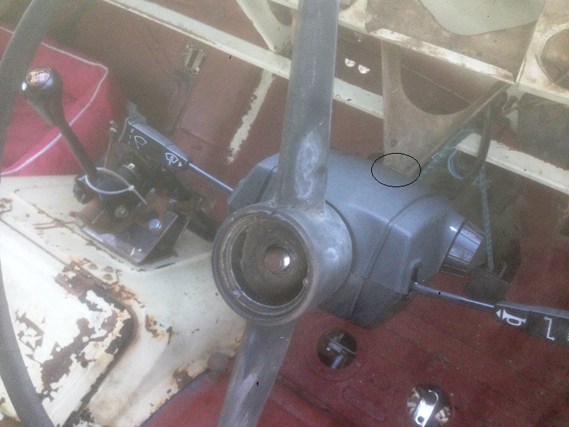
I had to cut a slot in the top section for the steering column support bracket, about 1" long and it sits neatly on top of the bolt and nut there. Matches up well to the bottom of the steering wheel too. Will need to sort a bracket to keep it in place. Need to look at mounting the Triumph ignition switch next, which has the key on the left hand side of the column. The little arm on the column shaft that knocks the indicator off after a turn will need a minor adjustment too. Will need to cut off part of the bottom of the instrument pod as the surround extends down past where it sits, job for tomorrow, and update then.
Cheers Stephen
Yes I have a surround for the Indicator/Wiper stalks Panky.
I had to cut a slot in the top section for the steering column support bracket, about 1" long and it sits neatly on top of the bolt and nut there. Matches up well to the bottom of the steering wheel too. Will need to sort a bracket to keep it in place. Need to look at mounting the Triumph ignition switch next, which has the key on the left hand side of the column. The little arm on the column shaft that knocks the indicator off after a turn will need a minor adjustment too. Will need to cut off part of the bottom of the instrument pod as the surround extends down past where it sits, job for tomorrow, and update then.
Cheers Stephen
Pleasantly surprised today as my VDO gauges arrived, so back out to the van to firstly trim the dash pod to fit around the Triumph column surround. With that done I fitted it back in the van and dropped the instruments in to see how it all looked.
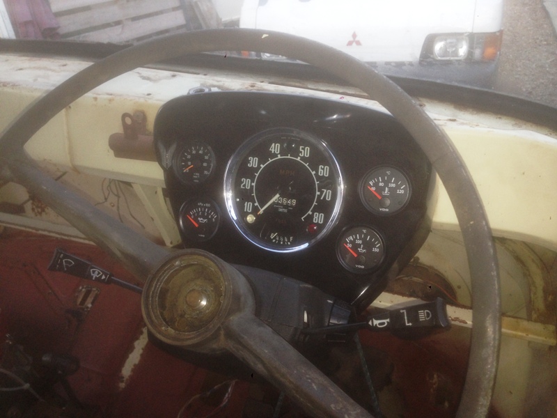
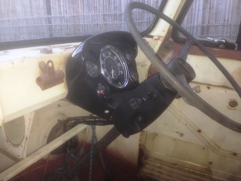
Pretty pleased with the result so far, still some fiddling to do and then of coarse wiring it up. Original steering wheel has to go eventually, will search the forums as I suspect the question has been asked before, what steering wheel fits on a Commer.
Cheers Stephen
Pretty pleased with the result so far, still some fiddling to do and then of coarse wiring it up. Original steering wheel has to go eventually, will search the forums as I suspect the question has been asked before, what steering wheel fits on a Commer.
Cheers Stephen
Hi All, got a little side tracked this weekend, was planning on looking further into the idea of using the Triumph wiring loom. Started removing the Triumph loom when I decided to remove the steering column so I had better access. With the column out things were easier and finally had the loom laid out on the rear lawn and looks promising. Returning to the Triumph I looked at the outer column tube and wondered if it was the same size as the Commer, as it would be so much easier mounting the stalks etc on the original column. Well they are almost the same, probably 1-2 mm difference in diameter and also longer, so decided to cut and replace the original with the Triumph's.
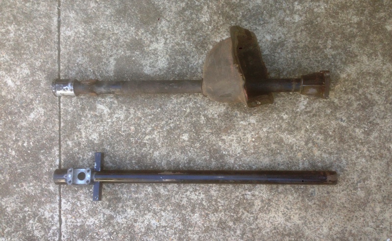
It was quite straight forward, some accurate measuring then cutting the original tube about 2" above the alloy section that bolts to the steering box and welding on the shortened Triumph tube. Sorry forgot to take a picture of that process. With that done I fitted the new column, all looked good. Now I pondered how to pack out the Commer felt bush for the top of the steering shaft, could have wrapped it in duct tape and fit it and never have a problem, job done. Then considered how and if it was worth trying to cut a slot for the Triumph ignition switch steering lock and eventually a steering wheel suitable. Well The conclusion was, if it's worth doing, it's worth doing right.
I decided to cut off the top 8.5 " of the Commer steering shaft and replace it with the Triumph's so I would have the steering lock slots and be able to use the Triumph's upper steering shaft bearing plus have the original arm for cancelling the indicator8s.
Step 1 Cut steering shafts to length.
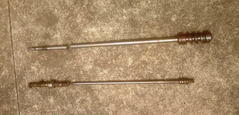
The Triumph's was cut to 8.5" long where the steering shaft has an existing weld, stepping down in size from 7/8" to 1/2"diameter. Then cut 8.5" off the Commer's. Both ends were ground back at 45 Degrees so the join when welded will be solid steel at through. Put one part with the other and you have this.
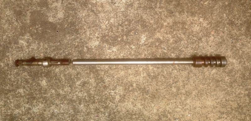
Welding the two parts was done by clamping them in the v of some 40mm angle to stop any distortion when welding, then tack welded and rotating and building up form there. It was important that the 2 shaft halves be orientated correctly prior to welding,. I stopped numerous times to grind down and clean up the weld before adding more and checking for straightness. Cutting and re-joining a steering shaft like this is something you shouldn't attempt unless you are a very good welder and you have a serious industrial welder. Once welded and cool I ground back any excess weld, cleaned and hit with a coat of primer.
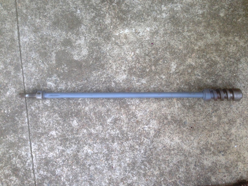
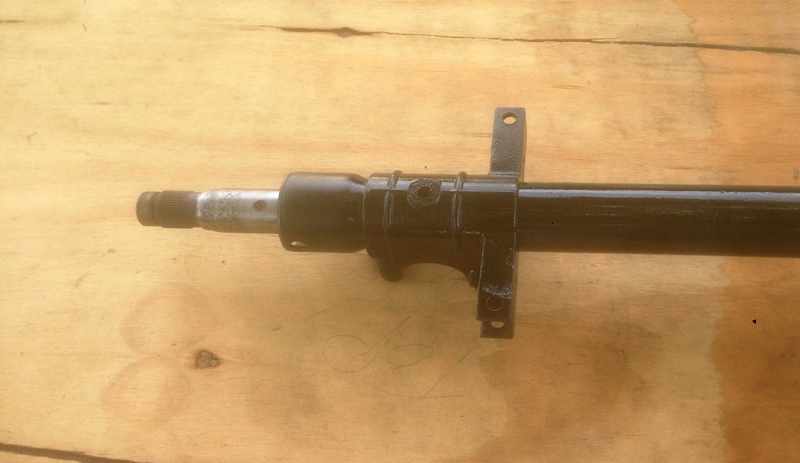
Once assembled this is the top of the column, showing the Triumph outer tube and steering shaft
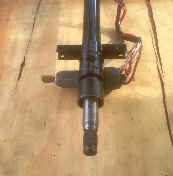
Add the ignition/steering lock
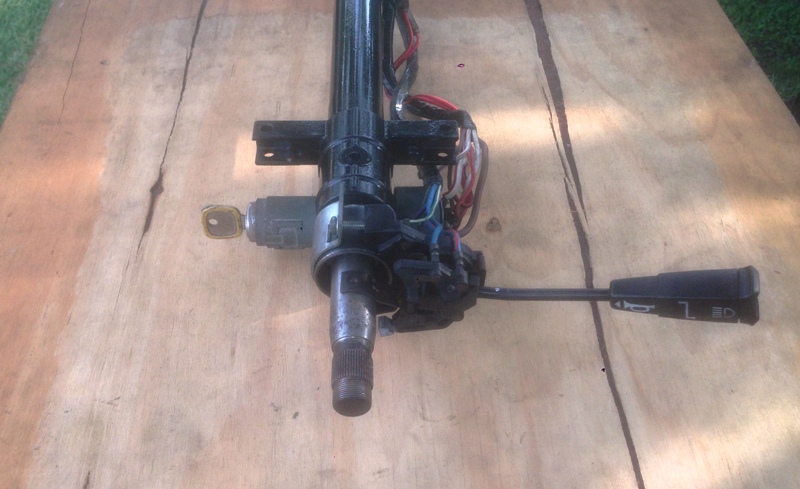
Then add the indicator/horn stalk
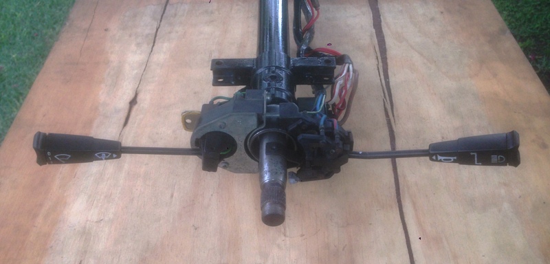
Then the Wiper/washer stalk
Then the lower section of the steering column cowl
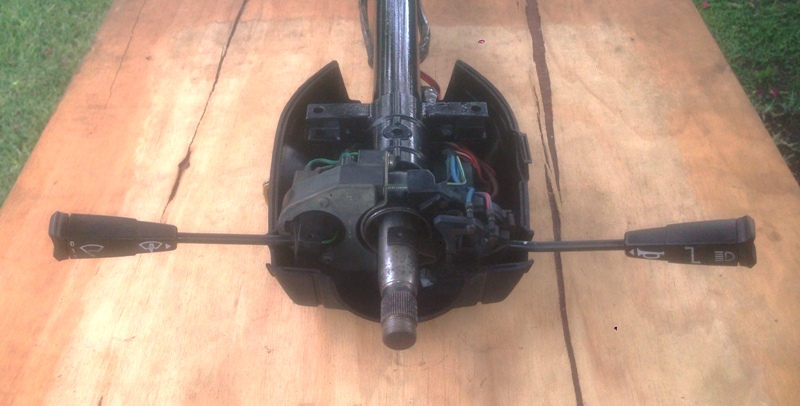
Then the upper cowl, which houses the park/head light switch.
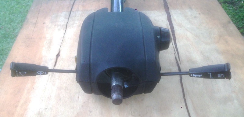
Top it off with a nice 15 " Triumph 2.5PI steering wheel and the jobs done
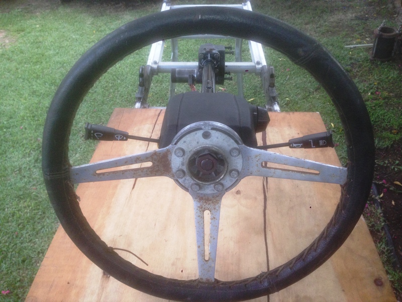
This all came from a 1974 Mk2 Triumph 2.5PI and would expect easier to get and cheaper at the wreckers for you lot in the UK. The 2.5PI head light switch has 2 additional positions, compared to the lower spec 2000 & 2500 TC's One position is intended for street park lights, turns on the drivers side parking lights only and a second position for UK dimmed main beam for city use, which hopefully I will be able to utilise if I use/adapt the Triumph loom to the Commer.
Very happy with the outcome, though realised later I forgot to fit the rubber boot for sealing the column to the floor. Well I had to forget something didn't I.
Cheers Stephen
It was quite straight forward, some accurate measuring then cutting the original tube about 2" above the alloy section that bolts to the steering box and welding on the shortened Triumph tube. Sorry forgot to take a picture of that process. With that done I fitted the new column, all looked good. Now I pondered how to pack out the Commer felt bush for the top of the steering shaft, could have wrapped it in duct tape and fit it and never have a problem, job done. Then considered how and if it was worth trying to cut a slot for the Triumph ignition switch steering lock and eventually a steering wheel suitable. Well The conclusion was, if it's worth doing, it's worth doing right.
I decided to cut off the top 8.5 " of the Commer steering shaft and replace it with the Triumph's so I would have the steering lock slots and be able to use the Triumph's upper steering shaft bearing plus have the original arm for cancelling the indicator8s.
Step 1 Cut steering shafts to length.
The Triumph's was cut to 8.5" long where the steering shaft has an existing weld, stepping down in size from 7/8" to 1/2"diameter. Then cut 8.5" off the Commer's. Both ends were ground back at 45 Degrees so the join when welded will be solid steel at through. Put one part with the other and you have this.
Welding the two parts was done by clamping them in the v of some 40mm angle to stop any distortion when welding, then tack welded and rotating and building up form there. It was important that the 2 shaft halves be orientated correctly prior to welding,. I stopped numerous times to grind down and clean up the weld before adding more and checking for straightness. Cutting and re-joining a steering shaft like this is something you shouldn't attempt unless you are a very good welder and you have a serious industrial welder. Once welded and cool I ground back any excess weld, cleaned and hit with a coat of primer.
Once assembled this is the top of the column, showing the Triumph outer tube and steering shaft
Add the ignition/steering lock
Then add the indicator/horn stalk
Then the Wiper/washer stalk
Then the lower section of the steering column cowl
Then the upper cowl, which houses the park/head light switch.
Top it off with a nice 15 " Triumph 2.5PI steering wheel and the jobs done
This all came from a 1974 Mk2 Triumph 2.5PI and would expect easier to get and cheaper at the wreckers for you lot in the UK. The 2.5PI head light switch has 2 additional positions, compared to the lower spec 2000 & 2500 TC's One position is intended for street park lights, turns on the drivers side parking lights only and a second position for UK dimmed main beam for city use, which hopefully I will be able to utilise if I use/adapt the Triumph loom to the Commer.
Very happy with the outcome, though realised later I forgot to fit the rubber boot for sealing the column to the floor. Well I had to forget something didn't I.
Cheers Stephen
Time for an Update. Finished off the steering column and while it was out replaced the output shaft seal and gave it a coat of black paint, so all good there. Went to have a look at the Triumph wiring loom some more and then discovered I couldn't find my Factorty workshop manual, only the parts book. so no wiring diagram, bugger! I know there are a few of you out there with Triumphs, anyone have or know someone with the wiring diagram for a 74 Triumph 2.5PI, had a look around the internet and haven't been able to find one yet.
So without any action there, I was pleased to receive a box of exhaust pipe fittings and mufflers last week, so got cracking with that. Box contained numerous mandrel bent bends, some flanges and 2 mufflers, a 16" resonator and a 16" offset/straight though muffler, all 2.25" diameter. Starting marking and tacking up the flanges off the extractors to a flex pipe then the resonator and muffler. A lot to fit in a limited amount of space, but managed to get these all in the straight section coming back from the motor.
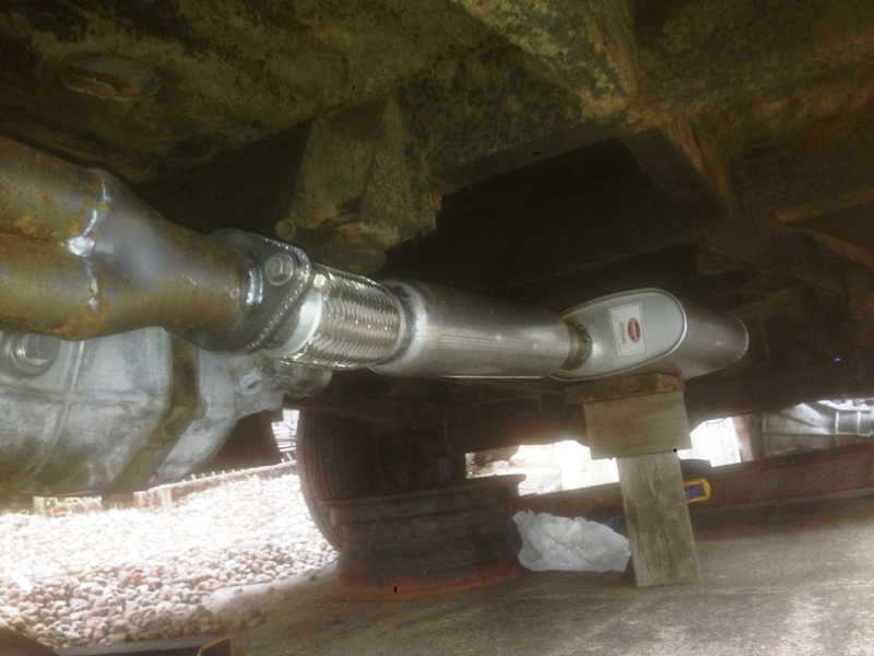
Next was the trick part, figuring out where the exhaust was going to run and ensuring it had adequate clearance where it crosses over above the tail shaft and getting the 4 mandrel bends of differing angles to stay in position so I could mark it and remove for welding. With the help of some rolled up cardboard that was a snug fit slid up each section, where they joined, I could manipulate the fittings until I had the fit I wanted. Removed it all tacked it up and refitted to check and was spot on. Removed it all again and welded it up. This is the final result.
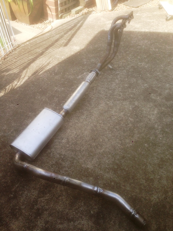
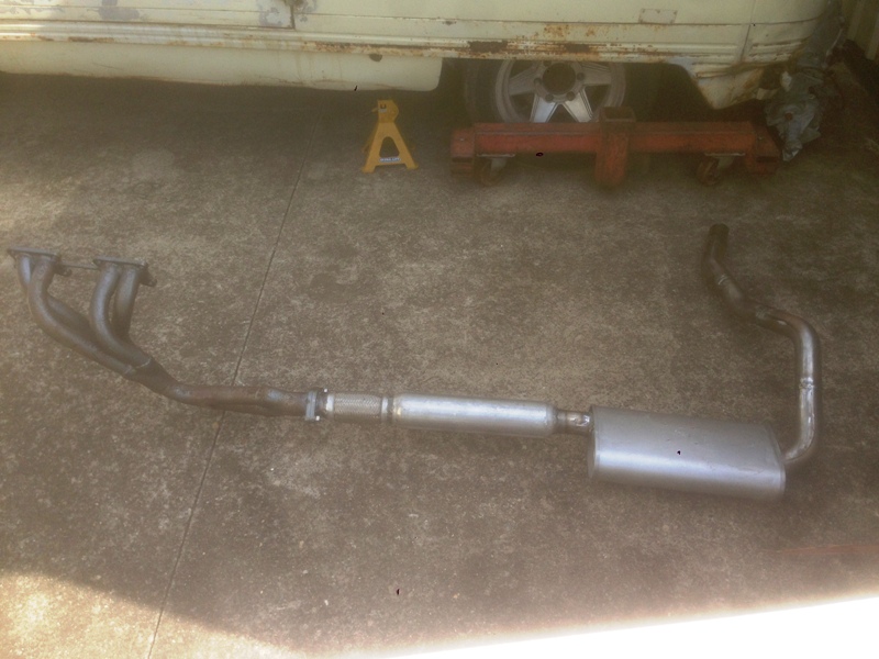
The length of the resonator and muffler meant that after the exhaust goes over where the tail shaft will be, the exhaust angles forward before again angling rearward to the end of the exhaust. Can be seen better in this picture.
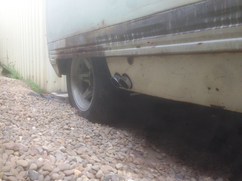
Have always thought the exhaust exiting under the side skirt of a Commer looked a bit odd, so have decided to exit through the skirt with a nice chrome twin 2.5" dump tip.
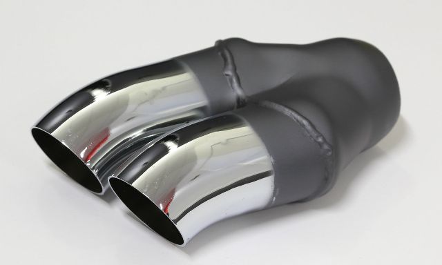
This will come through the skirt around or slightly rearward of the rear drivers side jacking point, with the pipes only protruding an inch at most past the skirt, nicely angled down and to the rear. Still have this final touch to do, as I have some mounts and supports to complete on the exhaust to hold it all nice and securely in place so there are no rattles.
Cheers for now
Stephen
So without any action there, I was pleased to receive a box of exhaust pipe fittings and mufflers last week, so got cracking with that. Box contained numerous mandrel bent bends, some flanges and 2 mufflers, a 16" resonator and a 16" offset/straight though muffler, all 2.25" diameter. Starting marking and tacking up the flanges off the extractors to a flex pipe then the resonator and muffler. A lot to fit in a limited amount of space, but managed to get these all in the straight section coming back from the motor.
Next was the trick part, figuring out where the exhaust was going to run and ensuring it had adequate clearance where it crosses over above the tail shaft and getting the 4 mandrel bends of differing angles to stay in position so I could mark it and remove for welding. With the help of some rolled up cardboard that was a snug fit slid up each section, where they joined, I could manipulate the fittings until I had the fit I wanted. Removed it all tacked it up and refitted to check and was spot on. Removed it all again and welded it up. This is the final result.
The length of the resonator and muffler meant that after the exhaust goes over where the tail shaft will be, the exhaust angles forward before again angling rearward to the end of the exhaust. Can be seen better in this picture.
Have always thought the exhaust exiting under the side skirt of a Commer looked a bit odd, so have decided to exit through the skirt with a nice chrome twin 2.5" dump tip.
This will come through the skirt around or slightly rearward of the rear drivers side jacking point, with the pipes only protruding an inch at most past the skirt, nicely angled down and to the rear. Still have this final touch to do, as I have some mounts and supports to complete on the exhaust to hold it all nice and securely in place so there are no rattles.
Cheers for now
Stephen

Looking good 
"You,re only supposed to blow the bloody SLIDING doors off"
Founder of the 6 speed club
"You,re only supposed to blow the bloody SLIDING doors off"
Founder of the 6 speed club



That looks very nice!
'I intend to live forever - so far, so good'
'I intend to live forever - so far, so good'

Hi All
With the exhaust system out of the way I took some bravery pills and started looking at the wiring. As mentioned earlier I have removed the wiring loom from my "spare" Mk2 Triumph 2500pi in the hope I can utilise this, with its additional features in the Commer. Well, so far so good. I unwrapped sections of the loom so I could reposition various wires so they could be positioned to suit the different layout in the engine bay. As it has come from a car, quite a few of the wires will need to be shortened, and only a few lengthened. Looks a bit like a colourful spider web at the moment, but it does make sense.
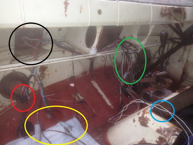
The Black circle shows the small panel from the Triumph that locates the fuse box, with 4, yes that's 4 fuses! This position in the Commer is basically the same as in the Triumph, and there are threaded holes in the internal rib that I will be able to use, most likely there for the regulator and fuse on LHD Commers.
The wires in the red circle that come from the fuse box are for the rear of the car and will connect up where the existing rear loom starts. I might change that over eventually to the Triumph rear loom as it has a few extra wires, like half way along is the connections for the Roof cabin light, then to the rear there is wires for the electric fuel pump, heated rear window demister, boot light, low fuel level & fuel tank sender, but will stick with sorting the front for now.
The wires in the green circle are those that go to the Triumph centre console, Cigarette lighter, 2 speed fan switch, switch for the heated rear window demister, choke on warning switch. I think there's a power feed for the clock here too. One wire to relocate in this group is the handbrake warning light switch, which should be pretty straight forward, just need to mount a switch on the handbrake.
Below the Green circle are the cables for the engine bay. I have split this group so in the blue circle we have the wires for the Ignition coil and resistor, tacho and water temperature sender. The group of wires that will travel down the other side of the engine bay will be for starter motor and solenoid, alternator, Low oil Pressure switch. Down this side I will need to add a few wires for the oil pressure & Temp senders and a power feed for the thermo fan.
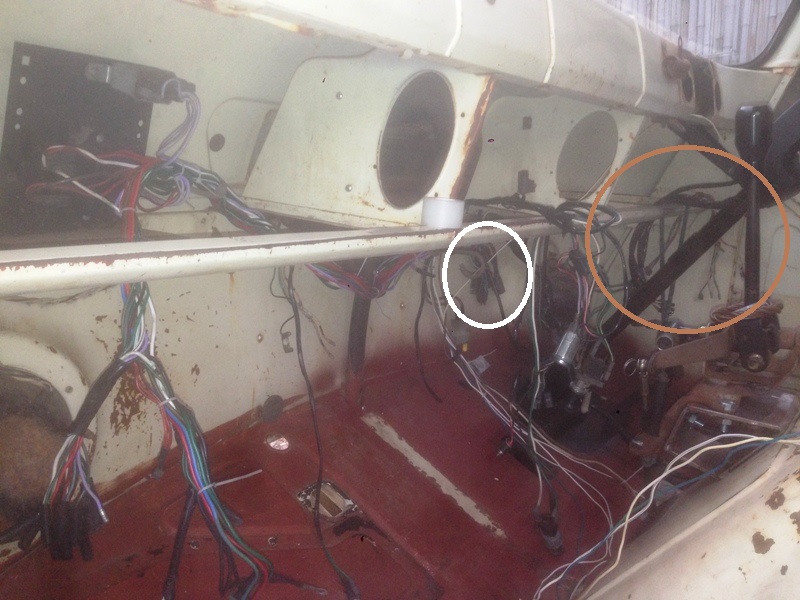
Lining up nicely behind the steering column, unfortunately obscured by the cigarette lighter and other wires are the 4 loom connectors for the column switches from the Triumph I fitted earlier, including the ignition switch, headlight main switch, indicators/hi-beam and wiper/washers/horn.
The smaller white circle shows the 3 loom connectors for the instrument panel loom.
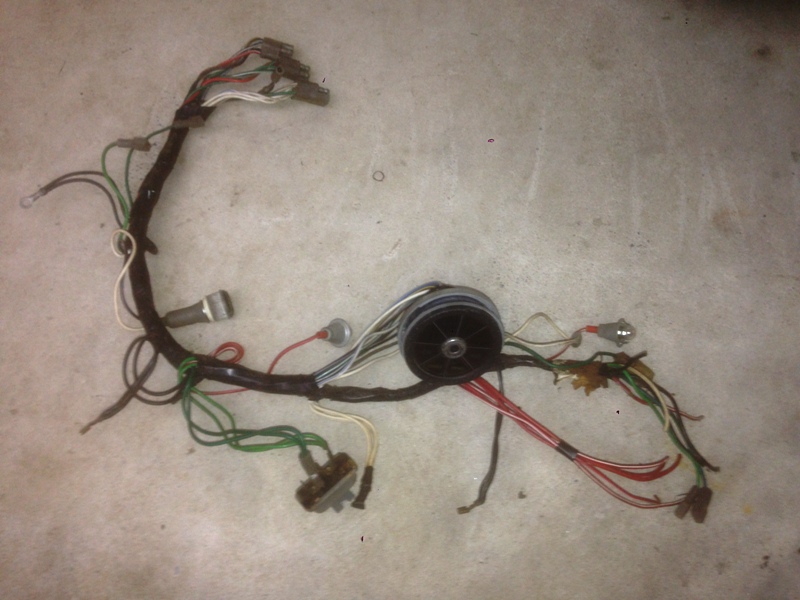
There is plenty of length on the instrument panel loom and will need to shorten many of the wires this loom carries the usual wires for instrument lights, fuel and water temp gauge, Hand brake warning light, low fuel, low oil pressure, hi-beam warning, and ignition warning lights. The bonus is that it also includes the voltage stabiliser which I will need for the original fuel gauge.
The loom continues under the dash to the driver side of the car for the wires that run to the headlights, indicators and horns. On the Triumph it exits under the driver side "A" pillar and runs forward then across the front to all the light etc, and is about 12 feet long, so plenty to play with there.
Just another thing, I was thinking about the front indicators, as mine is an early model with the single clear combined park/indicators. With the proliferation of LED lights available these days, I jumped on to ebay and had a look about and found these combined white/amber globe replacements.

How cool, I can have clear parking lights, which flash amber when turning. I found some for sale in the UK for $20 each + another $20 delivery. I then looked further and found someone in the Philippines selling them for $2.60 each and $2.75 postage for 4 globes to Australia. It's a crazy world we live in these days! Ordered the 4 globes and they arrived safely about a fortnight later. Here's the link if any one is interested http://www.ebay.com.au/itm/New-12V-BAY15D-1157-60-SMD-White-Amber-LED-Light-Bulb-Car-Tail-Brake-Signal-/121553809976. I have been told that I might need to install a resistor in line so the flasher can works, but hopefully if I leave the rear indicators and tail light globes as standard, that might be enough. Plenty to do before then.
That all for now, will keep plodding and update as things progress
Cheers Stephen
With the exhaust system out of the way I took some bravery pills and started looking at the wiring. As mentioned earlier I have removed the wiring loom from my "spare" Mk2 Triumph 2500pi in the hope I can utilise this, with its additional features in the Commer. Well, so far so good. I unwrapped sections of the loom so I could reposition various wires so they could be positioned to suit the different layout in the engine bay. As it has come from a car, quite a few of the wires will need to be shortened, and only a few lengthened. Looks a bit like a colourful spider web at the moment, but it does make sense.
The Black circle shows the small panel from the Triumph that locates the fuse box, with 4, yes that's 4 fuses! This position in the Commer is basically the same as in the Triumph, and there are threaded holes in the internal rib that I will be able to use, most likely there for the regulator and fuse on LHD Commers.
The wires in the red circle that come from the fuse box are for the rear of the car and will connect up where the existing rear loom starts. I might change that over eventually to the Triumph rear loom as it has a few extra wires, like half way along is the connections for the Roof cabin light, then to the rear there is wires for the electric fuel pump, heated rear window demister, boot light, low fuel level & fuel tank sender, but will stick with sorting the front for now.
The wires in the green circle are those that go to the Triumph centre console, Cigarette lighter, 2 speed fan switch, switch for the heated rear window demister, choke on warning switch. I think there's a power feed for the clock here too. One wire to relocate in this group is the handbrake warning light switch, which should be pretty straight forward, just need to mount a switch on the handbrake.
Below the Green circle are the cables for the engine bay. I have split this group so in the blue circle we have the wires for the Ignition coil and resistor, tacho and water temperature sender. The group of wires that will travel down the other side of the engine bay will be for starter motor and solenoid, alternator, Low oil Pressure switch. Down this side I will need to add a few wires for the oil pressure & Temp senders and a power feed for the thermo fan.
Lining up nicely behind the steering column, unfortunately obscured by the cigarette lighter and other wires are the 4 loom connectors for the column switches from the Triumph I fitted earlier, including the ignition switch, headlight main switch, indicators/hi-beam and wiper/washers/horn.
The smaller white circle shows the 3 loom connectors for the instrument panel loom.
There is plenty of length on the instrument panel loom and will need to shorten many of the wires this loom carries the usual wires for instrument lights, fuel and water temp gauge, Hand brake warning light, low fuel, low oil pressure, hi-beam warning, and ignition warning lights. The bonus is that it also includes the voltage stabiliser which I will need for the original fuel gauge.
The loom continues under the dash to the driver side of the car for the wires that run to the headlights, indicators and horns. On the Triumph it exits under the driver side "A" pillar and runs forward then across the front to all the light etc, and is about 12 feet long, so plenty to play with there.
Just another thing, I was thinking about the front indicators, as mine is an early model with the single clear combined park/indicators. With the proliferation of LED lights available these days, I jumped on to ebay and had a look about and found these combined white/amber globe replacements.
How cool, I can have clear parking lights, which flash amber when turning. I found some for sale in the UK for $20 each + another $20 delivery. I then looked further and found someone in the Philippines selling them for $2.60 each and $2.75 postage for 4 globes to Australia. It's a crazy world we live in these days! Ordered the 4 globes and they arrived safely about a fortnight later. Here's the link if any one is interested http://www.ebay.com.au/itm/New-12V-BAY15D-1157-60-SMD-White-Amber-LED-Light-Bulb-Car-Tail-Brake-Signal-/121553809976. I have been told that I might need to install a resistor in line so the flasher can works, but hopefully if I leave the rear indicators and tail light globes as standard, that might be enough. Plenty to do before then.
That all for now, will keep plodding and update as things progress
Cheers Stephen

If you're using LEDs as flashers, I think this is what you will need.......
http://www.vehicle-wiring-products.eu/product.php?xProd=631
Probably available local to you.
I think if you have a mixture of filaments and LEDs you won't get any warning if the LEDs fail, and certainly in the UK that is a requirement.
Commer PB Jennings
http://www.vehicle-wiring-products.eu/product.php?xProd=631
Probably available local to you.
I think if you have a mixture of filaments and LEDs you won't get any warning if the LEDs fail, and certainly in the UK that is a requirement.
Commer PB Jennings
Hi All, still working on the wiring, it's been slow and steady and piece by piece falling into place. Have completed the adaptation of the Triumph dash loom to my upgraded Commer dash, here it is before, yes that is a long dead spider in the top left.
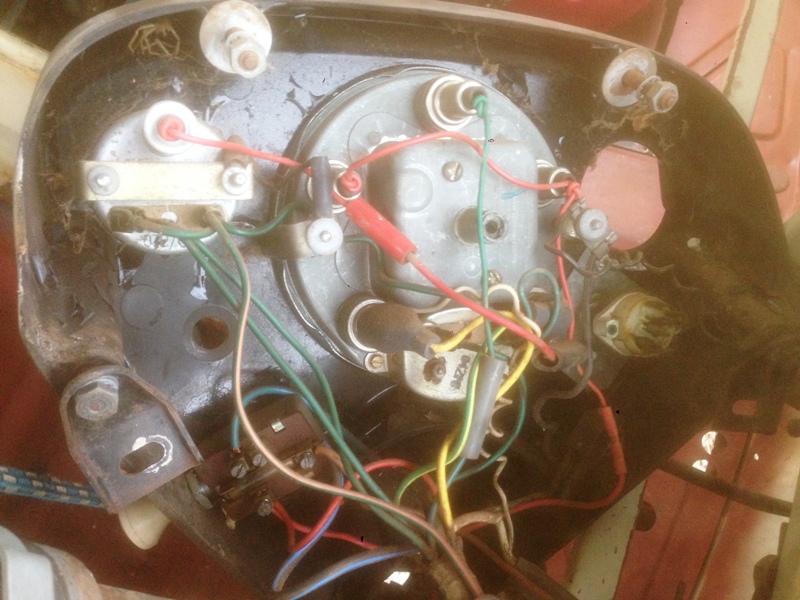
And after.
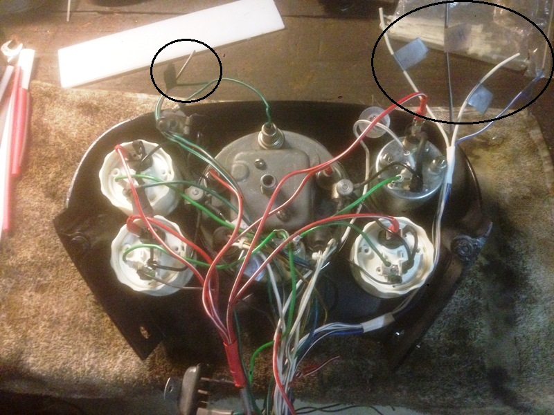
The 4 wires circled on the right are for the Low Fuel, Choke, Hi-beam and Handbrake warning lights. I'm currently trying to figure out where to locate then on the dash and find suitable warning lights.
The 2 wires circled on the left are for the indicator warning lights. I was originally going to use the indicator warning light in the Commer speedo for the Hi-Beam and have the indicators as separate left and right lights on the dash, but decided against this. The problem with using the single warning light is that joining the left and right warning lights would cause all the indicators to flash regardless of whether you select left of right. So I headed down to the local electronics shop to see if I could find a small twin filament globe and holder. As expected there wasn't. So ended up buying 2 clear LED lights and resistors I was advised to use and created my own for under $10. After a bit of soldering and heat-shrink for insulation and protection of the resistors I had a pair of globes that could fit in the original old lamp holder. I did need to strip the internals from the lamp holder and open the hole up where the wires entered it, but it all fitted quite nicely. I then set the globes in palace with Araldite so they wouldn't move and stayed centralised. Once set I tested them and they work great. Sorry no pictures for got at the time.
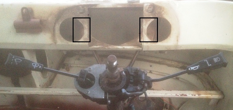
When I tried fitting the dash to the van the extra wires fouled on the metal panel behind, so I cut out the metal sections between the circular holes and the larger opening, which solved the problem.
Have ordered the 16 row oil cooler, fittings and 5 metres of hose, as I think I need a break from the wiring. I need to finalise the position of the remote Oil filter, which also has the sender units for the oil pressure and temperature gauges and low oil pressure warning light, so needs to be done so I can sort the wiring to the engine bay.
Cheers till next time
Stephen
And after.
The 4 wires circled on the right are for the Low Fuel, Choke, Hi-beam and Handbrake warning lights. I'm currently trying to figure out where to locate then on the dash and find suitable warning lights.
The 2 wires circled on the left are for the indicator warning lights. I was originally going to use the indicator warning light in the Commer speedo for the Hi-Beam and have the indicators as separate left and right lights on the dash, but decided against this. The problem with using the single warning light is that joining the left and right warning lights would cause all the indicators to flash regardless of whether you select left of right. So I headed down to the local electronics shop to see if I could find a small twin filament globe and holder. As expected there wasn't. So ended up buying 2 clear LED lights and resistors I was advised to use and created my own for under $10. After a bit of soldering and heat-shrink for insulation and protection of the resistors I had a pair of globes that could fit in the original old lamp holder. I did need to strip the internals from the lamp holder and open the hole up where the wires entered it, but it all fitted quite nicely. I then set the globes in palace with Araldite so they wouldn't move and stayed centralised. Once set I tested them and they work great. Sorry no pictures for got at the time.
When I tried fitting the dash to the van the extra wires fouled on the metal panel behind, so I cut out the metal sections between the circular holes and the larger opening, which solved the problem.
Have ordered the 16 row oil cooler, fittings and 5 metres of hose, as I think I need a break from the wiring. I need to finalise the position of the remote Oil filter, which also has the sender units for the oil pressure and temperature gauges and low oil pressure warning light, so needs to be done so I can sort the wiring to the engine bay.
Cheers till next time
Stephen