Replacing fuse board

Angus A

New Member
Hi all,

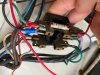
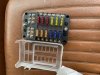
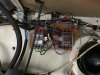
I'm looking at replacing the original "fuse board" on my 1973 Commer with something a bit more contemporary (aka safe!) with individual fuses for each circuit, lights, indicators etc. I've had a look in the workshop manual and I'm struggling to see the wood from the trees.

Has anyone replaced one of these before? The present set up is quite primitive with everything running through two fuses, I'm struggling to work out which wires are the lives from the main battery (assuming there are two?) and whether I can attach both lives to the positive of my new fuseboard (see pictures below). I'm not sure if the wires i've got are the original colours but I'm assuming the two browns will be lives.

Any advice very welcome!

Many thanks,
Angus
 

Attachments

  • IMG_3318.jpg
    IMG_3318.jpg
    92 KB · Views: 49
  • IMG_3319.jpg
    IMG_3319.jpg
    108.5 KB · Views: 39
  • IMG_3321.jpg
    IMG_3321.jpg
    99.7 KB · Views: 36
  • IMG_3322.jpg
    IMG_3322.jpg
    143.1 KB · Views: 42
The wires to the left of the original fuse board position are usually the live feeds, some are permanently live (top fuse I think) while others are only live with the ignition turned on.
To make sure which is wich your best advised to check with a multi-meter or test lamp so you can separate them out on your new fuse board..
The new looking black and green wires look like they are taking a feed from before the fuse (to accessories maybe) and, hopefully, have in-ine fuses added somewhere.
I did add a similar board to your new one but only used it for add-ons, surprising how quickly the positions fill up :rolleyes:
 
I was thinking of replacing too but haven’t got round to it yet. Out of interest what fuses should be in each one, one of mine has a 30 amp house fuse in so I do need to replace it with something more appropriate I think
 
Many thanks all for your really helpful comments and pictures, really informative! I’ll give this a go tomorrow and will let you know how I get on, I think it’ll end up being two different fuse boards for the two different circuits (permanently live, and live when ignition on)
Thanks,
Angus
 
It would probably make life easier with them split and you could add things like usb, stereo etc later and choose which feeds they ran off
 
It's a very good idea to replace the original fusebox Here's my set-up......................
DSCN0847.JPG
Although it looks complicated it's actually really simple. There are three 4 way fuse boxes. The left one is for lights. There's a 35 Amp master fuse at the top in the main feed to the light switch. That protects against short circuits at the light switch. That's the reason the old loom had burnt out) The other three fuses are for side lights, main beam, and dipped beam using the existing wiring.

The middle and right hand fuseboxes are for ignition-controlled and non-ignition-controlled circuits. The ignition controllled fusebox again has a master fuse at the top protecting the ignition switch and three fuses for individual circuits. The non-ignition-controlled does not need a master fuse because there is no switch to protect.

This re-uses the original wiring to the maximum extent, but I had to add a few wires to and from the switches. Oh, and by the way it's a diesel so you'll have to adapt a bit for petrol wiring. I can't recommend this type of fuse box either, as they are made for 1/4 inch diameter fuses which you can't get any more, aand the 6mm ones you can get don't fit properly Grrrrrrrrr!

Here's the fuse chart.............
DSCN0848.JPG

Hope this helps.
 
Thanks to all for your help with this and to Soupdragon for sending over the electrical diagram (I couldn’t find this in the manual on the site so very helpful! Seems like the headlights are cut off in the photo, do you by any chance have the rest of the diagram?) I spent an hour or so tracing lines with various colours of highlighter and managed to track what’s what in terms of wires (for the most part!).

All fitted and working now as two separate circuits (as advised - thanks for the tip!) photo below.

i also replaced the indicator and hazards relay with ones supplied by classic car LEDs.com which has worked brilliantly.

Next is to replace my cracked brake/stop light but struggling to find those anywhere online! Grateful if anyone knows where I can get some.

Pics below of new wiring set up, haven’t quite worked out what size fuse for each one yet but will get there in the end I’m sure!

thanks
Angus
 

Attachments

  • 9C32A08A-7D57-498E-9A97-5C9F8896BFEB.jpeg
    9C32A08A-7D57-498E-9A97-5C9F8896BFEB.jpeg
    3.6 MB · Views: 25
  • 5CD8E87D-5A3C-4850-8DBC-2DEBE92CC094.jpeg
    5CD8E87D-5A3C-4850-8DBC-2DEBE92CC094.jpeg
    3.2 MB · Views: 26
makes me want to do mine. Interesting about the short. I’ve just replaced the loom front to back as the rear light wire had burned out the length of the van. I assumed a short to body was to blame but you’re saying it was the switch on yours! Makes me worry it’s going to happen again. Can the light rocker switches be spilt and fixed or need to buy new?
 
Last edited:
Finally got round to doing mine. Horrible job and took ages. Replaced shelf for alu composite to take the bolts for angle board. Had used corner brackets epoxied onto board but bond failed when struggling to mount it right at the end. All extremely stressful and I’ve not tested it yet so it had better work or I’ll cry lol.
New constant live from battery and disconnected live from ignition to fuse board. Ignition live original. Decent-ve to body to future proof additions as they have a -ve buzz bar
28912FBE-7FFB-478E-977D-B9AFBD8C2274.jpeg0492F17A-E41C-4405-BEB1-DEF5AC2BB645.jpeg
 
Back
Top